With over 90,000 residents in Aylesbury and major expansion underway across the Vale, the pressure on marginal land has never been higher. Much of the town sits on a patchwork of Kimmeridge Clay, Gault Formation, and river terrace deposits along the Bear Brook, where loose granular layers and historic backfill create challenges for shallow foundations. The 2020s housing growth east of the A413 has pushed development onto sites where the natural ground simply cannot support working loads without improvement. Vibrocompaction design offers a proven path to densify these materials before construction begins, turning loose sands and gravels into a competent bearing stratum. Our geotechnical team brings experience from projects across Buckinghamshire, combining site investigation data with in-situ permeability tests to predict how the ground will respond to vibratory energy at depth. This is not a one-size-fits-all treatment — each design reflects the actual stratigraphy, water table position, and sensitivity of nearby structures.
A properly designed vibrocompaction grid in loose Thames Valley gravels can increase relative density from 40% to over 80% in a single shift, eliminating the need for deep foundations.
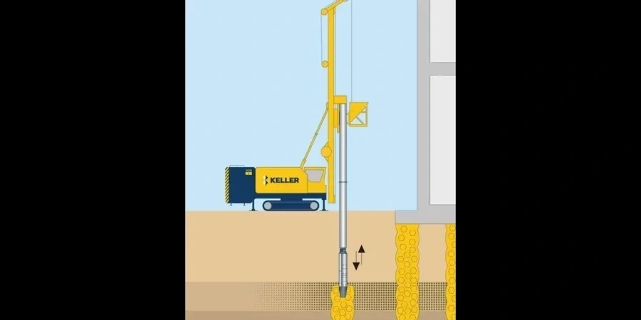
Approach and scope
Ground conditions shift noticeably across Aylesbury. The historic town centre near St Mary's Church sits on relatively firm chalk at shallow depth, while the newer development zones south of the railway line encounter metres of soft alluvium and made ground. This contrast demands a flexible approach: a vibrocompaction grid that works perfectly in the gravels near the Grand Union Canal may need complete reconfiguration just a kilometre east where the clay fraction increases. Our design process starts with a thorough review of CPT or SPT logs to map the thickness of the compressible layer. We then model the vibrator energy input — typically using a variable-frequency rig capable of 30–50 Hz — and determine the optimal probe spacing, typically on a triangular grid of 2.5 to 3.5 metres. The design output specifies the target relative density (usually 70–85%), the depth of treatment, and the sequence of passes. For sites where the water table sits within two metres of the surface, we incorporate drainage considerations and sometimes recommend a brief surcharge period after compaction to confirm settlement has stabilised. The chalk bedrock that underlies much of Aylesbury also plays a role: it acts as a rigid boundary that reflects vibratory energy upward, which can amplify densification in the lower portion of the treatment zone but may also transmit ground-borne vibration to adjacent properties if not managed carefully.
Q&A
What types of soil in Aylesbury are suitable for vibrocompaction?
Vibrocompaction works best in granular soils with a fines content below 12–15%. In Aylesbury, the river terrace gravels along the Thame and Bear Brook corridors, and the sandier facies of the Lower Greensand where it outcrops south of the town, are generally excellent candidates. The treatment loses effectiveness in the pure Gault Clay or Kimmeridge Clay — those require alternative methods like stone columns or rigid inclusions. A pre-design particle size analysis to BS EN ISO 17892-4 is essential to confirm the gradation before committing to the method.
How much does vibrocompaction design cost for a typical Aylesbury site?
For a standard residential or commercial plot in Aylesbury, the design package — covering the pre-treatment investigation specification, grid layout, energy modelling, trial panel design, and post-treatment verification interpretation — typically falls between £1,150 and £4,550. The final figure depends on site area, depth of treatment, and the number of verification CPTs required to satisfy building control. We quote each project individually after reviewing the available ground investigation data.
How long does the vibrocompaction design process take from start to finish?
Once we receive the ground investigation data, the initial design and grid layout can be completed within five to seven working days. The trial panel specification adds another day or two. The overall programme is then driven by site access: the trial panel execution and verification testing usually require three to five days on site, after which we interpret the results and issue the production design within two to three working days. For a typical Aylesbury plot, you should budget about three weeks from instruction to production-ready design.
Can vibrocompaction be used close to existing buildings in Aylesbury's conservation areas?
Yes, but it demands careful vibration monitoring and often a reduced-energy protocol. In Aylesbury's conservation areas — particularly around the historic core near Market Square and the Victorian terraces of Cambridge Street — we typically set a peak particle velocity limit of 10 mm/s at the nearest foundation, measured with real-time seismographs. If modelling shows that standard compaction energy would exceed this threshold, we adjust the vibrator frequency, reduce the lift thickness, or switch to a partial-depth treatment with a surcharge phase. In some cases, a vibration isolation trench along the boundary can attenuate surface waves sufficiently to protect adjacent structures.